Feature
|
Configuration Tables |
Data Sheet D2
|
Wiring |
History |
Feature Notes |
Datasheet |
|
|
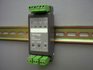
DHW Controller |
Latest released version is 4d1(beta 4dz)Document last updated 11/11/2002
|
DHW / DIN / 3T / ... |
Main FeaturesControls DHW TemperatureOptimum Start ControlOn-board outputs can drive Plant LocallyLPHW, Electric or Direct Gas Fired Calorifiers can be controlledPasteurisation/Sterilisation routine to kill bacteria |
 |
Input 3-4 |
Top of Tank / additional Sensor |
Input 5-6 |
Tank Sensor |
INMD = 0 |
|
SACT = 0 |
Control on tank sensor only |
SACT = 1 |
Control on average of two sensors |
SACT = 2 |
Control on maximum of two sensors |
SACT = 3 |
Control on minimum of two sensors |
Input 3-4 |
External occupancy VFC input |
Input 5-6 |
Tank Sensor |
SACT = 0 |
|
INMD = 1 |
Occupancy determined by Time Schedule AND external i/p Use for Interlock with high limit stat |
INMD = 2 |
Occupancy determined by Time Schedule OR external i/p Use for external occupancy override |
INMD = 3 |
External occupancy signal only Use for external timeclock control where no Zone controller used |
Input 3-4 |
External monitor / alarm VFC input |
Input 5-6 |
Tank Sensor |
SACT = 0 |
|
INMD = 4 |
Monitor Input if ALRM = 0 |
INMD = 5 |
Pump readback monitor |
ALST = 0 |
0 = Alarm State, 1 = Normal |
ALST = 1 |
0 = Normal, 1 = Alarm State |
Parameter ref |
Mnemonic |
description |
units |
default |
range |
C173 |
PTDW |
Pasteurisation Day:day of week for pasturisation, monday 1: sunday 7 |
day |
0 |
1 to 7 |
C174 |
PTST |
Pasteurisation Start Time, 24 hour clock set to nearest tenth of an hour |
hours |
0.0 |
0.0 to 24.0 |
C175 |
PTPD |
Pasteurisation Period: time in hours for which the water temperature
needs to be pasturised
|
hours |
0.0 |
0.0 to 4.0 |
C176 |
PTSP |
Pasteurisation Temperaturemust be non zero to activate pasturisation |
°C |
0 |
0 to 90 |
C177 |
PTOK |
Pasteurisation completed correctly |
- |
0 |
read only |
NOAL |
No Alarms.
|
SENF |
Sensor Failed. |
RPVF |
Remote Process Variable Failed.
|
EXTN |
External alarm generated by VFC input. |
PMPF |
Pump Fail (readback alarm) generated
|
STOP |
System STOP alarm received.
|
PTCF |
Pasteurisation Cycle Failed |
Option |
Output A |
Output B |
Output C |
/ 101 |
Time Proportional Heat |
Not used |
Occupation Switch or |
/ 105 |
Valve Open |
Valve Close |
Occupation Switch or |
/ 108 |
Sequence 2 triacs at 33% and |
66% of demand |
Occupation Switch or |
/ 109 |
Sequence 3 triacs at 25%, |
50% and |
75% of demand |
/ 110 |
Time Proportional Heat |
Immersion Heater |
Occupation Switch or |
/ 111 |
Valve Open |
Valve Close |
Immersion Heater |
Input Configuration |
|
Input 3-4 |
DHW Top Sensor (optional) |
Input 5-6‘temp’ |
DHW Sensor |