Feature
|
Configuration Tables |
Data Sheet (STD) |
Wiring |
History |
Feature Notes |
Datasheet |
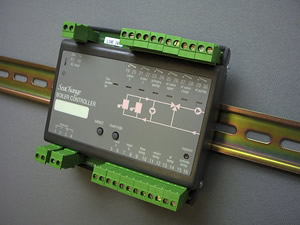
Boiler Controller |
|
Latest released version is 4c6Document last updated 19/05/2004 |
BLR / DIN / STD / .../... |
Main FeaturesControls 2 Boilers and associated plantUp to 8 Boilers in one sequence using Boiler Cascade SubmodulesSelf adapting Weather CompensationSystem Housekeeping function optionBoiler plant operates on demand from the building, not fixed time programme
|
 |
Input 9-10 |
Flow Sensor |
Input 11-12 |
Return Sensor |
Input 13-14 |
VT Sensor |
Input 15-16 |
Outside Sensor |
SACT = 0 |
Control on flow or return or average if both sensors valid |
SACT = 1 |
Control on Flow sensor only |
SACT = 2 |
Control on Return sensor only |
SACT = 3 |
Control on average of Flow and Return sensor values |
CRNG = 0 |
Disables Zone Trim and Adaption. |
TRNG = 0 |
Disables Zone Trim and Adaption. |
ZBST = 0 |
Disables Boost Mode. |
MIND = 0 |
Ensures VT pumps run constantly during occupancy. |
MODE = 0 |
Primary Pumps run for BRON period. |
MODE = 1 |
Primary and VT Pumps run on and VT Valve open for BRON period. |
MODE = 2 |
Primary and VT Pumps run on and VT Valve open and Zone valves overridden
to 100% for BRON period. |
NOAL |
No Alarms. |
GENA |
General Alarm on VFC input ‘a’ |
GENB |
General Alarm on VFC input ‘b’ |
LOKA |
Lockout Alarm on VFC input ‘a’ |
LOKB |
Lockout Alarm on VFC input ‘b’ |
FREZ |
Danger of Freezing alarm. |
STOP |
System STOP alarm generated. |
OUTF |
Outside temperature Fail alarm. |
FROS |
Frost protection in progress. |
Status Monitoring Only |
The status of inputs can be read on parameters |
Boiler Stage Shutdown, no Alarms |
Often used for Maintenance switches, or |
Boiler Lockout Alarm |
Used for Lockout signals |
Boiler General Alarm |
Used for General alarm signals |
General Plant Shutdown, Stop Alarm |
Used for external critical alarms |
Boiler Shutdown, or Master Off Alarm |
Used for external critical alarms |
Input 5-6 |
VFC input ‘a’ |
Input 7-8 |
VFC input ‘b’ |
ALRM = 0 |
Inputs used for monitoring only |
ALRM = 1 |
Inputs used for maintenance |
ALRM = 2 |
Inputs used for Lockout alarms |
ALRM = 3 |
Inputs used for General alarms |
ALRM = 4 |
Inputs used for STOP alarm |
ALRM = 5 |
Inputs used for STOP or Master Off |
H |
Heat Source |
20 |
C |
Cool Source |
20 |
A |
AHU Controller |
50 |
Z |
Zones |
100 |
M |
Monitoring Modules |
25 |
S |
Communications |
4 |
R |
Routers |
4 |
Option |
Function |
Max Cascade Submodules |
Max PCO Submodules |
/ SH / 001 |
With duty and sequence rotation, with housekeeping |
4 |
3 |
/ SH / 003 |
With fixed sequence, with housekeeping |
4 |
3 |
/ NH / 004 |
With duty and sequence rotation, no housekeeping |
2 |
1 |
/ NH / 006 |
With fixed sequence, no housekeeping |
2 |
1 |