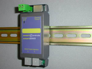
Feature Notes

smartServer

Features new this issue are in RED text

WEB/DIN/STD

Main Features

A simple supervisor in a module

The smartServer is the supervisor you do not need to engineer

The smartServer is the supervisor that does not require any special software on the PC, any internet browser will do

The smartServer is the supervisor which can run on a handheld Pocket PC

Summary Features

General

The smartServer provides 'plug and play' Ethernet (Internet) connectivity to a SeaChange Control system, and removes the requirement for bespoke or specialized 'Supervision' software. The entire system can now be monitored and maintained via a web browser interface, minor operational adjustment can also be made via WAP devices. No knowledge of HTML is required, all the pages are predefined and generated in real time, though a degree of customisation is available if required.

Features

Automatically generates system configuration views.
Allows adjustment of area time profiles and holiday patterns.
Graphical displays temperature data (with time/data indication).
Allows access to all standard configuration parameters.
Generation of e-mail on alarm for remote reporting.
Provides access to SeaChange System for 3rd party client.

Description of Features

The smartServer connects to the system via a standard serial adaptor. Once connected it discovers the modules and interconnects in the system to allow it to automatically present the supervisor pages. The first page presents all the Master Zone Controllers and the primary Heat and Cool sources.
The default names Zone 1 etc can be customised to match the names of the areas which are being controlled. The current temperatures, the occupation state and the temperature history are available for all the displayed items on this top page.
This is part of the plot for Zone 2 showing the early morning recovery on the DHW controller.
The underlined text indicates a hyperlink to another page, when this area of the screen is clicked the new page is presented.
The occupancy status of each zone can be overridden and the clock symbol can be selected to allow setting of occupation profiles and the system clock.
If the Zone is the Master for holiday purposes then the calendar icon is shown which allows setting of holiday periods anytime in the next year.
The required temperature can be set plus or minus 2 degrees from its current setting.
The pages have a standard set of icons along the top, which provide the following links:
return to the previous page
home, return to the Zone list
refresh the current page
configure smartServer
alarms
All the standard engineering parameters can be accessed by selecting the more link.
If sub-modules are registered then they are listed at the bottom of the page, the parameter icons replicate the buttons in InSite and allow access to configuration, sensors, inputs, knobs, switches. Configuration parameters are shown here.

System Structure automatically depicted

InSite broke new ground with a PC program that could be used to document any smartkontrols system and show the system structure in a number of views. The smartServer automatically organises it's pages to show the same relationships.
Zone 2 and Heat Source 1 have expansion symbols against them which indicate that further modules are related to them.
Selecting Zone 2 shows the details for Zone 2 but listed below are other Zones which are being supervised by this Zone, In this case the M on the Occupancy icon indicates that if the occupancy times are changed for Zone 2 then the occupancy times will also be changed in Zone 5.
Selecting Heat Source 1 shows the details for this Heat Source and also shows that Zone 1 and Zone 5 send their heat demands to Heat Source 1. Cool demands can similarly be tracked if the system includes cooling plant.
All the pages shown above are created automatically by the smartServer, a few minutes spent setting up some device names transforms the presentation into a user interface which can be used by anyone, the building has become a web site.

Monitoring and control points

The smartServer detects monitoring modules on the attached SeaChange system, the input and output channels can then be individually associated to Zones. The newer monitoring modules offer the facility for remotely controlling its outputs the smartServer will detect modules with this facility and determine if the input channels are analogue or digital automatically. The smartServer will spot any changes made to the monitor modules configuration, but the user can force the smartServer to relearn simply by pressing the register button on any product. (This process normally takes around 5 minutes for a normal system.)
 

Connectivity

The smartServer connects to any TCP/IP Ethernet network, if a network already exists in the building then all that needs to be done is obtain a suitable IP (internet protocol) address from the network administrator and connect the smartServer to the network via a 10 base T connection at the nearest hub. Once connected, enter the IP address in your browser and the job is done.
If the building does not have a Ethernet network consider using a WIFI (802.11b) wireless network, the base station plus one card for the PC can be purchased for less than £350. Connect the base station to the smartServer using a crossover Ethernet cable, plug the radio card into the PC or laptop and provided the PC is within range 50-100 meters you are connected. Large sites would need multiple base stations in order to provide site wide coverage. WIFI support is available on many handheld computers, which together with the built in browser allows access to the system anywhere within the WIFI coverage.
Using standard Ethernet products the networking options are limitless, for example a suitable router which provides connectivity to the internet would allow access to the system from any browser in the world. Security features allow all changes to be password protected.
Dial out connections to the internet can be used to send e-mail alarms to a remote location.

Specification:

Web Browser Requirements/Compatibility

The browser must support:-

Network Behaviour

The following figures are given as a guide to the network loading produced by the smartServer, these will vary dependent on traffic loading of the hosts network.

Web Server operation.

The web server uses HTTP 1.0 protocols to serve pages to the client web browser. These pages are dynamicly produced in real time, content and size will vary due to the configuration of the SeaChange system to which the server is connected. However as a guide an average page will produce 25000 bytes of data in 250 packets on the network. This can be divided down further as approximately half these packets are TCP acknowledgment's and 10000 bytes are the EtherNet header, this implies a typically packet from the server will carrying 120 bytes of data. Larger pages will produce more packets but due to the server operation this typical packet size will be maintained.
Images from the server. The largest graphical icon served is 2570 bytes and this will (if the network allows) result in a maximum packet size of 1024 bytes, the typically size for graphical icon's served is around 500 bytes. To reduce the loading on the server and the network the server will force the web browser to use cached version of the graphics when ever possible.
Client operation (InSite - Doorway Client) In this mode the standard SeaChange message packets are routed over the network in a EtherNet wrapper for processing by the remote server. Due to operation knowledge of the clients we can expect a single client to produce around 10 packets/per second on a receptive network, totaling around 700 bytes of network traffic. The addition of a second client will increase these figures by 20%, the addition of further clients will not significantly increase the amount of network traffic as the serial link between the server/gateway and the connected SeaChange system becomes the limiting factor in its ability to turn around client requests.

Commissioning : Quick setup guide for smartServer

Setting the Ethernet IP address

The smartServer is shipped with a default IP address of 192.168.1.200. Unless you have any operational need to change the smartServer IP address, we would suggest you leave it at its default setting.
Connect the smartServer to your PC using the supplied serial cable (RJ11 to 9 way D), you do not need the Ethernet connected at this point.
Now ‘click‘ [ok], if the smartServer is powered you should see random messages in the terminal window.
Power cycle the smartServer, after this ‘press’ [Carriage Return] three times.
The terminal will clear and the prompt ‘IP=192.168.1.200’ will be displayed, carefully enter the new IP address xxx.xxx.xxx.xxx and then ‘press’ [Carriage Return]. The terminal will now display IP Set to xxx.xxx.xxx.xxx.
Disconnect the PC and reconnect the smartServer to the serial adaptor.
Note the server Subnet mask parameter is fixed at 255.255.255.0 which should be suitable for all small/home networks.

Serial Adaptor settings

The serial adaptor parameters are factory set and should need no adjustment. The relevant parameters are listed:

Setting to work

Ethernet

Connect the smartServer to the network, the green lamp on the top face of the smartServer Ethernet connector (RJ45) should be ‘on’ permanently, if the network connection is active.
The yellow lamp on the left of the connector will flash to indicated activity on the network.
Using Microsoft Internet Explorer it should now be possible to browse the smartServer, enter its IP number in Internet Explorer address box and ‘press’ [Carriage Return] the smartServer home page should be displayed.

SeaChange

It is assumed that the SeaChange modules that comprise the control system have been commissioned at this point, and the smartServer is connected to the serial adaptor.
Power cycle the smartServer, after a short delay the serial adaptor ‘Tx/Rx’ lamp should be seen to flicker, as the system is interrogated. After a few minutes this lamp should be seen to pulse approximately every 5 seconds, indicating the attached SeaChange system has be learnt.
Now with Internet Explorer call up the smartServer home page, and ‘click’ the [continue] button to browse the control system.

Setting the real time clock

In the top right corner of the Internet Explorer window locate the following icon ‘Clicking’ on this will take you to the smartServer setup page.
Enter the correct time and date and then ‘press’ the [Set Time/Date] button. This process causes the server to restart, to display the new values ‘click’ on the refresh icon.

Email Alarms

To enable reporting of alarms via Email ‘click’ the [Advanced setup] button on the bottom of the setup page.
Enter the ‘Send alarms to field’ i.e. recipient@somewhere.com, if the field is not blank the smartServer will attempt to report alarms via email.
The ‘Alarms from’ field should be the name of the sending mail account.
WWW Gateway should be set to the IP address of the network Internet connection point (ZyXEL Router).
Mail Port number should be left as 25, unless advised otherwise.
Final enter the ‘Location of SMTP server’, this is your account mail server IP address, and your service provider should be able to provide you with this information.
Do NOT forget to ‘press’ the [Save setup] button, or your changes will be lost.

Customising your smartServer

Having completed the above the smartServer is now fully configured all that remains is to customise the pages to suit your property, not every one will know Zone 1 is the living room.

Change the page title

Every page has a common heading which represents the name of the property, by default this is ‘smartKontrols smartServer’.
To change this name ‘click’ the setup icon half way down the page is the ‘location name’ field, enter the property name here, now ‘press’ [Save setup] button at the bottom of the page.

Changing device names

In the middle of the setup page (remember ‘click ’ from any page ) ‘press’ [Change device name & grouping] button.
Using the drop down menu at the top of the page select the device you wish to change the name of, the page will refresh with the current details for that device.
The ‘Name’ field will show the devices current name, enter the actual room name, to save your changes ‘press’ the [Save changes] button.
Repeat this process for other devices.
Notice you can also specify how the areas are associated with each other and have IP based cameras, images or web pages link to specific devices, additional monitoring and control points, and lighting integration this is covered in advanced customisation.


Windows Dialup Networking

This last section is optional but allows for dialup connection via Windows Dialup Networking.
Select Menu 14
Enter Menu selection number {1}
You must also section the Modem direction to ‘Both’ or ‘Incoming’ under Menu 2 – Modem setup.
If the Remote PC is configured with a fixed IP, compatible with the local Network you can omit the next step, however If the Remote PC is configured for dynamic server assigned IP operation you must make the following changes at the ZyXel router.
Select Menu 13
Set IP Pool = 192.168.1.50
Note the IP address shown above is an example only and will depend on your Network configuration, however it is suitable for use with the ZyXel router and Smart Server in default configurations.

Options and Product Codes

smartServer Web Server Module

WEB / DIN / STD / [option]

Options

Option

 
/ 001
Standard version


ENER-G Controls

ENER-G House
Daniel Adamson Road
Salford
Manchester
M5 2DT

phone 0161 7457450
fax 0161 7457457

www.energ.com
www.seachange.co.uk
www.smartkontrols.co.uk