Feature Notes
|
Zone Controller
Master and Slave types
|
Features new this issue are in RED
text
|
ZON / PTR / LCD /... / ...(master types)
ZSL / PTR / LCD / .../ ... (slave types)
|
Main Features
Controls Space Temperature in a Zone
Optimum Start and Stop Control
User Interface for any type of plant
Engineering Display for Commissioning
|
 |
 |
 |
Summary Features
General
Large Clear Display shows System Status and
Current Settings
Settings easily made using Dedicated Push Buttons and Rotary
Adjustment Knob
2 Time Periods per Day: 7 Days per Week
Special settings for Today and Tomorrow
Holiday Period Feature
Can be used to remotely display values from another module
Can use temperature values from other modules for control
Can be used to supervise the operation of other plant
Condensation control for Chilled Ceilings
Fabric Protection using temperature or Relative Humidity
Can be used to display Alarms from the system
External inputs for remote sensors or Occupancy Override
signals
Master / Slave operation
Both Zone Controllers and Slave Zone Controllers are available.
Slave Zone controllers take all of their time settings
from a (master) Zone Controller, and hence do not have the relevant time control
buttons.
Users may still adjust their temperature setpoints and
use the Override & Time Extension features.
Slave Zone Controllers perform their own Optimum Start
function independent of the master Zone Controller.
Up to 100 Slaves can be associated with one Zone Controller.
Description of Features
User Display Options
The Zone Controller can be used to display certain other parameters
in the system which can be particularly useful to installers and maintenance
staff.
Viewing User Displays
To view user display parameters:
-
Press and hold select button
-
Rotate Knob clockwise to show parameters.
Preset (factory default) parameters are:
1
|
Room Temperature
|
ROOM
|
2
|
Required Temperature
|
REQD
|
3
|
Zone Control Demand
|
DMND
|
4
|
Outside temperature
|
OUTS
|
5
|
Boiler flow temperature
|
FLOW
|
6
|
Time & Day
|
MON-SUN
|
Release button:
-
Display will continue to show parameter selected
To return the display to Room Temperature
-
Press & hold select button
-
Rotate Knob anti-clockwise to beginning of list to
show ROOM
-
Release button
Changing User Displays
It is possible to reconfigure two of the user display parameters
- Nos 4 & 5
- to read other system parameters than those preset. This can be used to display
temperatures from other modules e.g. POOL temperature or DHW temperature.
Put zone into configuration mode and select required parameter
on target module by:
-
Pressing & holding select + override buttons until
status display flashes
-
Press select on target module
-
Press & hold select on Zone Controller
-
Rotate Knob until Required Temperature value shown
-
Release select button
-
Press start 1 & stop 1 buttons together to change user
display 4 (preset to Outside Temperature) a tick symbol will appear in the
display.
-
Press start 2 & stop 2 buttons together to change user
display 5 (preset to Boiler flowtemp) a tick symbol will appear in the display.
-
Return Zone to normal mode - press select and override
together.
To Reset User Displays to Factory Defaults
-
Put Zone into config mode
-
Push pair of buttons used to set particular variable
i.e.
start 1 - stop 1 for user
display 4
start 2 - stop 2 for user display 5
-
Copy & holiday for Room Temperature Process Variable
(see below)
-
Display will temporarily show RSET to show variable
has been reset
-
Exit from config mode
Confirming the Source of a User Display which
is already set up
To confirm where a user display is coming from, put the Zone
Controller into config. mode, select suspected target module, turn knob clockwise
with select button depressed to locate suspected value, if tick displayed this
is the displayed user value. If no tick displayed then value can be updated
by pressing the appropriate buttons together (see Changing User Displays).
Remote PV (Process Variable)
The Zone Controller normally uses the Room Temperature
either measured by its internal temperature sensor or a remote sensor wired
into its terminals as the Process Variable that the Zone will control.
It is possible to use a temperature measurement being made by
another module in the system as a Remote Process Variable in place of the Room
Temperature. The Zone Controller accesses this information from the other module
over the communications network.
The Zone Controller will then display the new value and 4-character
label (e.g. POOL from a Pool Controller or HW T from a DHW Controller)in
place of the ROOM temperature.
To set Remote Process Variable:
-
Press and hold select + override buttons on Zone until status lamp flashes
(Zone in Config Mode)
-
Press select on target module
-
Press and hold select on Zone Controller
-
Rotate Knob clockwise until target temperature value shown
-
Release select button
-
Press copy & holiday buttons together.
-
A tick symbol will appear in the display
-
Unit will now display and work to new process variable.
Note this variable must be a measured temperature parameter.
Do not try to use a remote setpoint as a Process Variable by this process.
Be careful if using the Zone Controller to perform the control
of the temperature, because the Zone Controller Fuzzy Logic constants are set
assuming a slow moving Room temperature and may not cope well with a fast changing
temperature.
Alternatively, this feature may simply be used to remotely display
an appropriate value (if, for instance the Zone Controller is being used to
set Return Air Setpoint in an AHU Controller using Setpoint Supervision, then
the measured temperature RTNA from that module should be displayed on
the Zone). In this case, the HTSC and CLSC parameters in the Zone
Controller should be set to zero, to disable spurious Energy Demand signals
to other modules (because the control is being done by the AHU module, not the
Zone).
See also Temperature Sensors and Occupancy Inputs for details
of Networked Temperature Sensors.
Temperature Control
Optimum Start (OPST)
The Occupation Time periods define the times that the building
or zone will be to temperature and suitable for occupation.
The Controller will bring on the heating services or HVAC system
for a boost period before the beginning of the occupation period to bring the
building to the required temperature. The boost period is varied depending on
both the zone temperature and the outside temperature in order to bring the
zone just up to the required temperature by the beginning of the occupation
period. This feature is known as optimum start. By changing the boost time,
energy is saved as the plant does not run longer than actual conditions require,
the Zone Controller adapts the parameters in its optimum start algorithm so
it learns the characteristics of the building and of the services plant.
The Zone learns different characteristics for heating and cooling
modes because the plant will have different characteristics in each mode.
Two Parameters can be adjusted to affect Optimum Start; MXOS
is used to limit the length of the boost period. With undersized plant, it may
not be possible to reach the Occupied Setpoint on very cold days without an
excessively long boost period, so the length of the boost period may need to
be limited.
The OPTE parameter may be used to allow the Optimum Start
algorithm to aim for a setpoint lower than the Occupied Setpoint; this is useful
where a step change in heat gain occurs at Occupancy Start, due to lots of people
entering the space (e.g. schools) or equipment being turned on. The use of the
OPTE parameter can prevent temperature overshoot under these conditions.
During the Optimum Start period the figure on the display jumps
in and out of the house.
Optimum Stop
The services for a zone can often be turned off before
the end of occupation without the temperature falling outside acceptable conditions.
The optimum stop control algorithm calculates how long before the end of occupation
the services can be switched off based on zone temperature, outside temperature
and its learned characteristics of the building.
The maximum optimum off period is preset to 2 hours configurable
by MXOF. Setting the parameter of 0 disables the optimum off function
which is the preset. Note that the optimum off function turns off the heating
or cooling only . Fresh air and ventilation plant would continue to run until
the normal end of the occupation period. The target temperature for optimum
off can be offset from the Required Temperature by setting the configuration
parameter SBDB - preset to 0°C.
During the Optimum Stop period the figure on the display flashes
ON and OFF inside the house.
Required Temperature
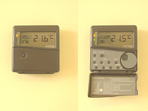
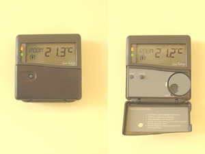
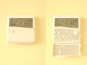
The Zone Controller normally displays the Room temperature.
To View and Change the Required Temperature
-
Rotate the adjustment knob by one click; the display shows Required Temperature
(REQD). After a few seconds the display reverts to Room Temperature
(ROOM) displayed.
The Required Temperature is preset to 20°C; to change the
Required Temperature rotate the knob more than one click. Clockwise to increase,
anti-clockwise to decrease.
Intelligent Setpoint
The Zone Controller has a number of functions that limit
the adjustments that the user can make to the temperature in order to ensure
comfort and energy efficient operation are maintained.
Setpoint Adjustment Limit
Changes that can be made to the Required Temperature using the knob
are limited to 2degC at a time (the adjustment limit) to prevent users unthinkingly
making large adjustments that would impair the energy efficiency of the system.
After a few minutes the Required Temperature can be altered further. The adjustment
limit is a configuration parameter SPAJ which is preset to 2°C
Adjustment Range
The total Adjustment Range of the Required Temperature
is limited to prevent it being set to unacceptable conditions. The Adjustment
Range is preset to 5°C about the range midpoint temperature which is preset
to 20°C. The Adjustment Range and Midpoint can be set by configuration parameters,
SPRG & SPMD.
Required Temperature Reversion
At the beginning of each day the Required Temperature reverts
to its Default value so that any changes made the previous day are lost and
the control returns to an energy efficient default. The Default temperature
can be configured to be anywhere within the Adjustment Range and is preset to
20°C (configuration parameter SPOC). The Required Temperature Reversion
feature can be disabled by setting the configuration parameter SPDF to
zero.
Heat - Cool Control
The Zone Controller has the ability to control cooling
as well as heating and can work through separate plant and actuator controllers
for both heating and cooling.
It is normal to set a dead band between the heating and
cooling functions to allow the temperature to float between the two modes which
will improve energy efficiency. The dead band is configured by the SPDB
parameter. It is preset to 0 which disables the cooling control loop. Setting
between 1 to 10°C enables cooling control and sets the cooling dead band.
It is sometimes desirable to switch off the cooling control without loosing the deadband setting. This can now be done by changing the value of C84 ENCL ENable CooLing, this needs to be set to 1 to enable the cooling function. Note the code automatically sets this parameter if the deadband setting is set/changed to a non zero value.
Fabric Protection - using Temperature
During the occupation period the Zone controls to the Required
Temperature. Outside the occupation period, the zone will bring on the services
if the temperature falls to the Fabric Protection Temperature in order to avoid
condensation forming.
Once the Fabric Protection algorithm has been initiated it will
bring the temperature up by the Fabric Rise Temperature in order to avoid the
plant cycling ON and OFF. The Zone remains in this mode until the temperature
has risen by the amount specified by the parameter FRSE at which point
the Zone Controller reverts to non-occupied setpoint as before. If a stable
temperature is required during non-Occupancy (e.g. night setback for a nursing
home) then FRSE can be left set to the factory default setting of zero.
The Fabric protection temperature is a configuration parameter
SPNO and is preset to 10°C.
When the Zone is running the plant in Fabric Protection mode
a snowflake symbol appears on the display.
Fabric Protection - using Relative Humidity
If a Networked T+RH sensor is registered to the Zone Controller,
the Humidity value may be used for Fabric Protection; the Zone Controller can
be made to bring on the heating to prevent RH levels rising above a predetermined
level.
The Humidity reading can be read from another module by setting the controller to receive the RH value on USR1 or USR2 values, see above and then setting C149 RHPV to 1 or 2 to indicate which parameter contains the RH value.
The desired maximum RH level is set on parameter SPRH
(Rh setpoint); setting a non-zero value will enable RH Fabric Protection
If the RH is below the RH setpoint, the Zone will control to
its normal non-occupied setpoint (set on SPNO) as for temperature-based
Fabric Protection. As the RH in the space rises, the Zone Controller will increase
its current setpoint (which can be read on Monitoring Parameter REQD)
at a maximum rate of 0.1 degC per minute according to an integrating control
action. As this temperature setpoint exceeds the current temperature in the
space, so the heating will be enabled, raising the temperature and thus reducing
the Relative Humidity. The temperature setpoint is limited to the normal Occupied
setpoint for the zone (set on SPOC) thus providing a high limit for space
temperature.
Frost Protection
The Zone Controller is made aware of the Frost protection
status of the Boiler Controller. If the Boiler is in Frost protect this is communicated
to the zones which will display the frost symbol and open any registered actuators
to 50% and start any optimum start/stop switched loads. The Zone remains in
non-occupied (man out of the house) to distinguish this mode from Fabric Protection.
Two Pipe Control
When used in conjunction with
Heat Source HSCVT4d1 or later as its Heat Source the Zone Controller now allows
for Two Pipe heating and cooling. This Heating Secondary Controller must have
a temperature sensor connected to the Flow side of the two pipe system so that
it can broardcast the medium temperature to all it's registered consumers. The
4d1 range of secondary controllers also allows for interlocks between heating
and cooling versions so that the meduim can be controlled.
A new configuration variable TPSL
Two Pipe SeLect must be set to enable this feature, two modes are available.
(The minimum output feature MNOP has been removed) Remember the SPDB SetPoint
DeadBand also needs to be set to enable the cooling control. The Zone Controller
will display the medium Flow temperature from its Heat Source on the FLOW display.
Two Pipe Mode 1: mixed actuators
With TPSL Two Pipe SeLect set to
1, the Heating demand to the actuator controller will carry the Cooling Demand
if the meduim temperature at least 1 degree less than the controller mid point
setpoint. Normal Heating is resumed if the medium Flow temperature is at least
1 degree above the controller mid point setpoint.
Two Pipe Mode 2: intelligent
actuators
With TPSL Two Pipe SeLect set to
2, heating and cooling demands are sent to standard Actuator controllers as
normal. A new output signal is sent to all intelligent actuators registered
to the controller, this demand will be for cooling if the meduim temperature
at least 1 degree less than the controller mid point setpoint, and will be for
heating if the medium Flow temperature is at least 1 degree above the controller
mid point setpoint.
The new demand does not use the
normal Heat or Cool demands to the intelligent actuator so the heating/cooling
selection on the IA is not important.
The Zone Controller will display
the medium Flow temperature from its Heat Source on the FLOW display.
Occupancy Control
Time Schedules
The user can set the times that the Zone is to be used
- called occupation periods - by setting the time schedule. This allows 2 occupation
periods per day and different settings for each day of the week.
Preset times are
-
One occupation period: 0830 to 1700 Mon - Fri
-
No occupation: Saturday & Sunday
System Clock
All Zones share a common system clock function so on multi
zone systems it is only necessary to set the clock and day on one zone - all
the other zones will receive and use the updated time and day.
The Real Time Clock (RTC) is located in the System Housekeeping Module and this
module broadcasts the time information over the network every minute and this
is received and used by all modules that require this information. If the Zone
Module fails to receive the time update - (for instance if the System Housekeeping
Module is disconnected or is in configuration mode when it will not communicate)
then the zone will automatically switch to use its internal software based clock
until the time signals are restored.The Zone Controller alerts the user by bringing
an X symbol in the lower part of the display when it is running on its software
clock.
Setting the System Clock
To Set Current Time
-
Press and hold clock button
-
Rotate Knob until correct time shows on display
-
Release Button
To Set Current Day
-
Press and hold day & clock buttons together
-
Rotate Knob until correct day shows in display
-
Release Buttons
Setting the 7 Day Time Schedule
Select the Day to be changed
-
Press & hold day button
-
Rotate Knob to select day
-
Release button
View and adjust time periods
-
Press and hold Start 1 button
-
Display shows current start time for period one
-
Rotate Knob until display shows required start time
-
Release button
-
Set Stop 1 for end of period 1 in same way
-
Set second time period using Start 2 and Stop 2 in
same way (if required).
To skip an Occupation Period:
The controller will skip an occupation period if the start
and stop times are set the same. The default times are to skip the second occupation
Monday to Friday preset to 24:00 and both periods Saturday & Sunday preset
to 00:10.
Copy Feature
Having set the occupation periods for one day they can
be copied to other days of the week using the copy facility
-
Select the day to be copied from using the day button
-
Press and hold the copy button
-
Rotate Knob until last day in copy sequence shows in display
-
Release button
The occupation times have been copied, from the initial
day to all the days, including the final day in the sequence. The copy process
can go both forward (Mon to Fri) and back (Fri to Mon) depending on which way
the knob turned.
The variable display shows both the initial day and the final
day in the sequence as day number 1 - 7, Monday is day 1 and Sunday day 7, so
copy from Monday to Friday and the variable display will show 01:05
Today & Tomorrow
The time periods for today and tomorrow can be set to be different from
the normal 7 day time periods but they are volatile and the system will revert
to the normal 7 day time periods when they are over. This is useful for unusual
events (e.g. late working, or early starts) which are not repeated every week.
To set times for today and tomorrow
-
Select day
-
Press and hold day button
-
For TODAY rotate Knob Anti clockwise until display shows TDAY (for
Today) which is before MON
-
Ffor TOMORROW rotate Knob clockwise until display shows TMRW (for
Tomorrow) which is after SUN
-
Press start and stop buttons to display current time periods
-
Press and hold start and stop buttons and rotate knob to set special times
-
Release button
Override
Occupation Status is shown on the display During an occupied
period, the figure is in the house, outside occupation the figure is outside.
The user can Override the Occupation Status using the Override
Button that appears through the flap on the front of the controller.
The way the Override works changes depending on the periods of
the day when override is used.
If used before the beginning of either Occupation period in the
day, then the zone will be Occupied until the end of that Occupation period.
If Override is used when the zone is Occupied, then the unit will switch to
non Occupied until the start of the next time period. If Override is used after
the end of the Occupation periods then there will be a timed extension to the
Occupation period. This extension period is preset to 1 hour but may be changed
by using configuration parameter XHRS.
Switch 3 Master Override MOVR
When set any change in the Override settings initiated by pressing the
Override button on the Master controller will be sent to all Slave Zones. The
Slave Zones must be issue 4c or later for this to work. This feature is only
available on Master Zone Controllers.
If the Slave Zone is time slaved to a Master Zone Controller which has MOVR
Master Override set, then changes to the Override state of the Master will be
reflected in all the slaves controlled by that Master.
Holiday
The Zone Controller can be set to Holiday
Mode which is the number of days holiday period starting from the following
day. Occupation periods can be set for holiday (for cleaners etc.); the preset
value is for no occupation period.
To set Holiday Occupation period
-
Press and hold day button
-
Rotate knob clockwise until HOLS displayed - This is after SUN
& TMRW
-
Release day button
-
Press and hold start 1 button
-
Rotate knob to show required start time
-
Release button
-
Repeat for Stop 1 & period 2
To set Holiday Mode
-
Press and hold holiday button
-
Display shows number of days holiday starting from tomorrow
-
Rotate knob to display required number of holidays, 14 for 2 weeks etc.
-
Release button
When Holiday Mode has been set (but is not active, i.e on the last working
day) the display will indicate this by showing a flashing “Suitcase”
symbol. When Holiday Mode is active, the display will show steady “Suitcase”
and flashing “Seagull” symbols.
If the holiday setting is set to zero, either from Doorway or by using
the holiday button and the knob, the holiday mode is cancelled. If the Holiday
process is active, suitcase and seagull displayed, then the standard occupation
pattern is loaded for today otherwise the current today's times are retained.
If switch 4 MHOL Master Holidays is set then any change to the holiday
settings, at the controller or via Doorway will result in these settings being
sent to all Zone Controllers and DHW controllers on the whole system. It is
advisable to only activate this feature on one controller on the system. Similarly
setting HDAY to zero when MHOL is set will cancel any Holiday
setting throughout the system.
From issue 4c1 the number of days holiday is sent to all slave zones,
or to all zones if MHOL is set, this means that the holiday status is
now evident at each zone because the 'suitcase' and 'seagull' will be displayed
in the same way as on the master zone. Changes to the holiday settings are sent
after a 30 second delay, to give the user time to complete and check the change.
Extended
Holiday features
The range of the Holiday features
when changed from the network has been extended to 500 days also a special value
for HDAY -1, displayed as OFF on the Zone Controller, allows the Zone to be
put into Holiday (unoccupied) mode for ever. To set this from the Zone hold
holiday button and rotate anticlockwise past 0 to OFF. This provides a simple
method for Holiday Home owners to shut down the house until their next visit.
Two addtional configuration variables
have been added C168 RDAY RunDays and C169 SHOL StartHolidays. The operation
of these parameters is quite complicated and it is intended that they are only
changed by the Web Server. In essence Start Holidays provides a daily countdown
to the start of a non occupied holiday period the length of which is defined
by HDAY. RunDays provides for a number of days of normal occupation after which
the Zone will become permanently not Occupied. Using these two values and HDAY
the WebServer is able to set any length occupied or unoccupied period for any
time in the next year.
If trying to recover from miss set
parameters set RDAY and SHOL to -1 (OFF) to disable the feature. This can be
acheived using the knob by holding down Start 1 & Holiday to adjust SHOL
and Stop1 & Holiday for RDAY.
External
control of Holiday settings
If SACT is set to 8 then the external
contact input is used to set the Controller into and out of Holiday mode. This
contact can be wired to a security system or other Home Automation Controller.
The logic used allows subsequent setting of expected arival date using the normal
Holiday setting.
When the contact changes from open
circuit to closed circuit the Holidays setting is changed to -1 or OFF, providing
permanent Holiday mode.
When the contact changes from short
circuit to open circuit, if HDAY is still -1 then it is reset to 0 No Holidays,
otherwise no action is taken. This allows for HDAY to be changed in the intervening
period to represent the expected arrival date so that the building can be brought
back up to temperature prior to arrival.
Registration
The Zone Controller can be used in several different ways, for
Controlling the Zone temperature directly, for supervising other controllers
in various ways, or for demanding services from other controllers. Some of these
features are mutually exclusive, whilst some can co-exist at the same time.
The various forms of Logical Links between this Zone Controller
and other Controllers are made by the process of Registration; a brief description
of the process is given below. For a full description, see our CD ROM.
Address Allocation
Before any Registration Links can be made, the Zone Controller
must be allocated an address by the System Housekeeping Module. The Register
button is pressed; the Zone should display its address; “ZONE1”, “ZONE2”
etc.
Submodules
The Zone Controller may have up to 8 Submodules (e.g. Actuator
Controllers, Pump Changeover Modules) registered to it. The Zone is put into
Configuration Mode and the Submodule is registered to it. This sets up the Submodule’s
address (which will be of the form Zn Am , where n is the Zone’s address,
and m is the Submodule’s address).
The registration process also makes Control Demand links between
Zone and its Submodules, so that they will respond to Occupancy and Heating/Cooling
demand signals from the Zone as appropriate.
Networked Sensors
The Zone Controller may have a Networked Sensor registered to
it; either a Condensation sensor, a Networked Temperature sensor, or a Networked
Temperature + Relative Humidity sensor. Only one sensor may be registered to
a Zone. The Zone is put into Configuration Mode and the Sensor is registered
to it.
Demand Links
These links are Many-to One links made from this Zone (and
perhaps many others) to a Module that is providing a service to the Zone (provision
of Fresh Air, Energy or Domestic Hot Water services). They can each exist with
any other links simultaneously.
Occupancy Demand
The Occupation state of the Zone can be passed to an AHU
or DHW Controller using Occupancy Demand linking; this is for plant which provides
a service for many zones (e.g. Fresh Air plant). The Target Module is put into
Configuration Mode, and the Zone register to it. This sets up the Occupancy
Destination parameter OCDS to “point” the Zone’s Occupancy
Demand at the target, which will then run when the Zone (or any other Zone thus
registered) is in Occupancy. Occupancy Demand linking can be used in conjunction
with any other links at the same time.
Energy Demand
The Zone Controller can send its Energy Demands for Heating
and Cooling to another Module (a Distributor Module, like a Secondary Circuit
Controller or Provider Module like a Boiler Controller) if that Module is responsible
for providing energy to the Zone. The Distributor/Provider Module is put into
Configuration Mode, and the Zone is registered to it. This sets up the HTSC
and CLSC parameters in the Zone to “point” the Energy Demands
at the appropriate Modules. Energy Demand linking can be used in conjunction
with any other links at the same time.
Supervision Links
These links are One-to Many links made from this Zone to
one or many other Modules. The Zone Controller will supervise the behaviour
of these other modules in some way; either their Setpoint, Occupancy Status
(i.e whether they are On or Off) or their Time Schedules (so that they can still
perform their own Optimum Start and Fabric Protection). The Zone Controller
can only have one of the 3 types of link with any given Module, but it may have
links of each type with several different Modules concurrently (e.g. it can
supervise the Setpoint in an AHU Controller, and send Occupancy Times to a Slve
Zone Controller at the same time)..
Setpoint Supervision:
The Zone Controller can be used to transmit its Setpoint
to another Module (e.g. an AHU Controller) or to many other Contollers (e.g.
Fan Coils).
Parameters in the Supervised Modules will need to be set (typically
their SPTY parameter -see appropriate Data Sheets for details).
The SLVM parameter in the Zone must be set to 2 or 3 (a
setting of 3 will allow the Zone to also send Occupancy Times to a different
Controller). The Zone Controller is put into Configuration Mode, and the target
Controller(s) are registered to it. This Setpoint Master-Slave link will be
confirmed by “SLVE” (for Zones, Fan Coils etc.) or “SAHU”
appearing in the Zone’s display.
AHU Controllers thus supervised would normally run to the Zone’s
setpoint during Occupancy, and will turn off during Non-Occupancy. If it is
desired to run the AHU during Non-Occupancy (i.e for 24 hours) but at a different
setpoint, the parameter NOSV may be used ; if set to a non-zero value,
this will keep the AHU running at the desired setpoint.
Occupancy Supervision:
The Zone Controller can be used to transmit its Occupancy
Status to many other Contollers (e.g. Fan Coils). This mode of linking can be
used instead of Setpoint Supervision to drive Fan Coils on and off, but leave
them controlling to their own setpoints. The Zone Controller will be responsible
for Optimum Start and Fabric Protection.
Parameters in the Supervised Modules will need to be set (typically
their SPTY parameter -see appropriate Data Sheets for details).
The SLVM parameter in the Zone must be set to 2 or 3 (a
setting of 3 will allow the Zone to also send Occupancy Times to a different
Controller). The Zone Controller is put into Configuration Mode, and the target
Controller(s) are registered to it. This Setpoint Master-Slave link will be
confirmed by “SLVE” (for Zones, Fan Coils etc.) or “SAHU”
appearing in the Zone’s display.
Time Schedule Supervision:
The Zone Controller can be used to transmit
its Occupancy Time Schedules to many other Contollers (e.g. Slave Zone Controllers).
This mode of linking can be used instead of Setpoint Supervision to set Occupancy
Times but leave them controlling to their own setpoints, and performing independent
Optimum Start and Fabric Protection for their parts of the building.
Parameters in the Supervised Modules will need to be set (typically
their SPTY parameter -see appropriate Data Sheets for details).
The SLVM parameter in the Zone must be set to 1
or 3 (a setting of 3 will allow the Zone to also send Setpoints to a different
Controller). The Zone Controller is put into Configuration Mode, and the target
Controller(s) are registered to it. This Setpoint Master-Slave link will be
confirmed by “SLVE” (for Zones, Fan Coils etc.) or “SAHU”
appearing in the Zone’s display.
Temperature, RH and Occupancy Inputs
Conventional Thermistor Sensors
The Zone Controller (type /001) is fitted with its own
internal temperature sensor which is used as the measured temperature to be
controlled.
The unit can be connected to a remote temperature sensor which
is a conventional, low cost thermistor type for applications where it is inappropriate
to locate the Zone Controller in the area to be controlled because it may be
tampered with. The Zone Controller is preset to switch control to the remote
sensor if one is fitted but the sensor action parameter SACT can be set
so the controller uses the higher, lower or average value of the two sensors.
If one sensor fails the control will continue on the other sensor alone.
A version (/003) of the Zone Controller is available without
an Internal Temperature sensor but with the ability to use 2 remote sensors.
This is useful to provide freedom of location of sensors and to allow two measurement
points in a larger space.
Because they are standard 10K ohm thermistors, 4 can be wired
in series/parallel configuration to provide electrical averaging of 4 sensors.
Thus up to 8 sensors can be wired to a Zone Controller.
Intelligent Networked Sensors - Temperature
A SeaChange Intelligent Networked Temperature
Sensor (which has its own Microprocessor and derives its power from the network)
may be registered (as a Submodule) to the Zone Controller. The Zone will display
SEN1 when the device is registered. This type of sensor has the advantage
that it may be located anywhere on the network, and so may provide installation
benefits because an additional cable may not need to be run between the Zone
and the sensor. The parameter SACT must be adjusted accordingly to make
the Zone Controller use the Networked Sensor value as its Process Variable in
place of its own thermistor. Control will revert to the local thermistor if
the Networked Sensor reading is invalid.
Unlike the feature Remote Process Variable,
(described under User Display Options) where the Process variable is obtained
from another Controller Module, here the value is coming from a Sensor Submodule,
so the Zone Display will still read “ROOM”.
Intelligent Networked Sensors - Temperature + Humidity
A SeaChange Intelligent Networked T + Rh sensor connected
somewhere on the network may be registered (as a Submodule) to the Zone Controller.
The Zone will display SEN1 when the device is registered. The parameter
SACT must be adjusted accordingly to make the Zone Controller use the
Networked Sensor Temperature value as its Process Variable in place of its own
thermistor. Control will revert to the local thermistor if the Networked Sensor
reading is invalid.
The Relative Humidity may be used for Monitoring only,
or it may be used for enhanced Fabric Protection using Rh control - see Fabric
Protection.
Send own Temperature SNDT
When a Zone Controller is registered to an AHU controller which is set
to SPTY 2 then the Zone's temperature reading may be used as the Return
temperature reading for the AHU. The AHU might have many Zones registered and
might also be using an intelligent TRH sensor for its Return temperature reading.
To allow for these cases the Zone code has been changed so that sending the
Zone temperature needs to be enabled at the Zone using configuration value SNDT.
Do not set this if a) the AHU is using TRH sensor for Return Temperature or
b) if multiple zones are registered to the AHU only set SNDT on one representative
Zone. If you see the Return temperature cycling between one or more values then
check SNDT on any registered zones. SNDT is 0 (OFF) by default.
If the zone controller has a T_RH intelligent sensor registered to it and SNDT is set both the Temeprature and RH value will be sent to the AHU as the Return Air values.
Sensor Action
The parameter Sensor Action SACT allows considerable scope for
combining internal, external and networked sensor values. The min, max and average
options will use all the sensor values which are valid so for example the minimum
value would be the minimum of the in-built sensor, an external hard wired sensor
and a networked sensor if all were being used and were presenting valid readings.
Sensor Calibration
The sensor calibration can be trimmed using the SCAL parameter.
This provides a fixed offset to the temperature measurement and applies to the
resultant temperature - after selection of remote, average, etc. functions using
SACT parameter. Sensor calibration is preset to 0°C.
Switch Inputs
Remote Occupation Status Input
A Volt-Free Contact (VFC) may be wired to the external
input connections to provide external control over the Occupation Status of
the controller.
Occupancy/Non-Occupancy Switching
The remote temperature input connections can be configured
by SACT to be a remote input to provide occupation override. This uses
a contact closure (volt free contact) to drive the zone into the occupancy state
if it currently is not occupied but will not alter the occupancy state if the
time schedule etc., has already put the zone into occupancy. This feature can
be used to drive a zone into occupancy using an input from a simple switch,
another item of plant, or a Presence Detector or Card Access Controller. Note
that any timed on period should be part of the presence detector function, the
Zone Controller will revert to Non-occupied directly the signal is removed.
A new setting SACT 7 has been added which tests for normal Zone Occupancy
AND an external signal to be available for the Zone to enter Occupation. This
allows override OFF for non occupied periods to be set with a switch or interlocked
with other equipment in the panel.
Occupancy/Standby Mode Switching
The remote temperature input connections can be configured
by SACT to be a remote input to provide Occupation/ Standby Mode switching.
This uses a contact closure (volt free contact) to drive the zone into the occupancy
state if it is currently outside of its Occupation Times. If the Zone is in
its normal Occupancy period, with the external contact open circuit, it will
be running in Standby Mode (i.e with a wide deadband set on parameter SBDB).
When the external contact closes, the Zone will be driven into
its normal Occupation Mode (with a normal close deadband set on SPDB).
This feature can be used to drive a zone into occupancy using an input from
a simple switch, another item of plant, or a Presence Detector or Card Access
Controller. Note that any timed on period should be part of the presence detector
function, the Zone Controller will revert to Non-occupied directly the signal
is removed.
Condensation Control
The Zone Controller can control condensation in Static Cooling
(Chilled Ceiling and Chilled Beam) installations, where condensation can form
on the cold surfaces of the ceiling if the ceiling temperature is allowed to
fall below the dewpoint of the surrounding air. This phenomenon is sometimes
refererred to as “Office Rain”.
A SeaChange Intelligent Networked Condesation Sensor must be
registered to the Zone Controller (the sensor can be connected anywhere on the
network). Upon registration, the Zone Controller will display “SEN1”.
If the Condensation Sensor reports a condensing condition, the
Zone Controller will progressively ramp down its Cooling Control demand signal,
and hence start to close down any registered Actuator Submodules, which would
be controlling the Cooling Valve on the Chilled Ceiling. An alarm can also be
generated; see Alarm Handling and Display.
As the condensing condition clears, the Zone Controller will
resume normal control; thus a simple form of local Dewpoint Control has been
created. The Controller will allow the Chilled Ceiling to run as cold as possible
whilst preventing condensation, which will ensure that the maximum possible
cooling output is derived from the ceiling.
If the Condensation Sensor fails to respond or becomes disconnected
during a condensing event, the Zone Controller will recover normal operation
within 7 minutes, until the sensor is re-connected.
Alarm Handling and Display
The Zone Controller can generate alarms, and can also respond
to alarms sent by other Controllers. If it receives an alarm, it can be set
to take some control action, display the alarm, or both.
Alarm Generation
The Zone Controller can generate 3 different alarms, which
can be reported at Doorway Supervisor, or on the display of this Zone Controller
(see below).
SENF |
Alarm is generated when the sensor reading is outside of the allowable
range |
RPVF |
Alarm is generated if the Controller is set to use a Remote Process
Variable from another controller in place of its own sensors, and the
Variable is not being received across the network |
CNDF |
Alarm is generated when a Condensation sensor registered to this Zone
has detected condensation. |
Alarm Control Action
The Zone Controller can be set to react to alarms in different
ways; the ALRM parameter can be set to ignore alarms, to report alarms
but take no Control Action, or to shut down its Control Demand output (and hence
any registered Submodules’ outputs, e.g. Actuator Controllers) - either
because of an internal alarm, or because a System STOP alarm has been
received.
Alarm Displays
The Zone Controller can be set to display alarms if required.
The setting can make the Zone display only its own alarms, or alarms from any
other Controller on the network.
The parameter AMON when set to a non zero values enables
the Alarm Monitoring feature. The controller stores the first 10 Controllers
which report alarms and the display flashes “HELP” and the
current number of Controllers which have reported alarms, alternating with the
normal display (usually ROOM and the temperature value). If the Alarm
is generated by the Zone controller itself then the display will show the Alarm
label instead of HELP.
Pressing override acknowledges the alarm and the display reverts
to normal except that the screwdriver symbol continues to flash until the alarms
clear.
This feature has been developed to provide simple alarm indication
on small systems so that the occupants can alert their maintenance company that
there is a fault. Alternatively it can be used to show sensor fail or condensation
imminent for just the zone affected.
Accessing Configuration and Monitoring Parameters
Configuration Parameters are used to adjust settings from their
factory defaults; Monitoring Parameters are mostly used to monitor internal
readings (such as temperature readings) during the Commissioning process.
This Module’s Parameters may be viewed, and in the case
of some parameters, adjusted by one of two methods; Either by using the Zone
Controller’s own buttons and display, or by using the SeaChange Doorway
Supervisor. The Zone Controller may also be used to view parameters in any other
Module on the network.
Using the Zone Controller
-
The Zone Controller must be connected to the network and registered (see
Commissioning Guide for further details).
-
Put the Zone Controller into Configuration Mode by depressing Select
and Override buttons for 10 seconds, until the CNFG legend appears
on the display.
-
To view Parameters in this Zone Controller, miss out this step and go
to step d). To view Parameters in another Controller, press Select button
on the target device (in this case, the Boiler Controller).
-
Hold down Select button on the Zone Controller, and rotate the rotary
knob:
clockwise to view Monitoring Parameters
anticlock to view Configuration Parameters
-
When desired Configuration Parameter appears, release Select, hold down
Override and turn knob to adjust the parameter (note; some Monitoring Parameters
cannot be adjusted).
Note: Once you have selected another controller to view, you
can select another controller (by pressing its Select Button), but you cannot
“deselect” all other controllers in order to return to viewing the
Zone’s own parameters. In order to do this, exit from Configuration Mode
(press Select and Override briefly) then start again at step a) above.
Using SeaChange Doorway:
Data Points may be added to a Doorway page to access/adjust any
Configuration or Monitoring Parameter. Graphs of certain Parameters are also
available. The code used to access a Boiler Controller is Zn ,where n is the
Zone’s address number. The code for each parameter is shown in the Config
Tables.
Further details of how to set up Doorway pages may be found
in the SeaChange Doorway Manual, or in the online help facility supplied with
SeaChange Doorway.
The PC running SeaChange Doorway can be connected locally
via a Serial Adaptor Module, or remotely using standard High-Speed Modems; all
Parameters can thus be monitored and adjusted remotely.
Switch 5 Manual Hand control HAND
When set, the controller output will be determined by the value set
on the configuration parameter MANL. This may be changed between -100
full cooling output and +100 full heating output. This feature allows known
demand levels to be setup to check that all the relevant demand links have been
correctly made.
To activate put the controller into to configuration mode, hold the select
button down and rotate the knob clockwise until the switch HAND is displayed.
Hold down the Override button and set HAND equal to 1. The controller
will automatically exit configuration mode and display the MANL parameter
which may be set using the override button and the knob. If it is important
that a predetermined manual level MANL is used at the start of HAND
mode, select and change the Configuration variable MANL before setting
the switch HAND.
While in Manual Hand Mode the status led will fast flash and the Zone controller
will only display MANL and the demand value. The value may be adjusted
by holding down override and turning the knob. To exit Manual Hand Mode press
select and override together.
Using Doorway add a point with the following syntax
[Z1]W5(S)/hand/auto/12/10/C83(V)
This will normally display as auto, when clicked a dialog box will appear
which will allow hand to be selected and the level adjusted, the point will
change to hand when the controller is in Manual Hand mode.
Options and Product Codes
Zone Controller
ZON / PTR / LCD / [option] / [colour] (master types)
ZSL / PTR / LCD / [option] / [colour] (slave types)
Options
Option |
|
/ 001 / |
With internal sensor, provision for 1 remote sensor or override device |
/ 003 / |
With no internal sensor, for use with 2 remote sensors or 1 remote
sensor and an override device |
Colour Options
Option |
|
/ G |
Grey housing |
/ W |
White housing |
|
Input Configuration |
Input 3-4 |
Remote sensor or external VFC override (optional) |
Input 5-6 |
Remote sensor (optional, for / 003 types only) |
ENER-G Controls
ENER-G House
Daniel Adamson Road
Salford
Manchester
M5 2DT
phone 0161 7457450
fax 0161 7457457
www.energ.com
www.seachange.co.uk
www.smartkontrols.co.uk