Feature Notes

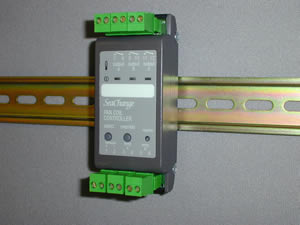
Fan Coil Controller
with 3x Triac Outputs (3T version)

issue 4d1
features new this issue are in RED

FCU / DIN / 3T/ [driver option]

Main Features

2 Pipe Fan Coils:
- Heating Only + Fan Enable
- Cooling Only + Fan Enable

4 Pipe Fan Coils:
- Airside Damper + Fan Enable
- Thermal Valves + Fan Enable

Works in conjunction with other SeaChange Controllers via “Plug-and-Play"


Summary Features

General

2 pipe fan coil controller (type / 001, / 002) for heating only or cooling only applications with fan enable.
4 pipe fan coil controller (type / 003) for fan coils utilising an airside damper with fan enable.
4 pipe fan coil controller (type / 004) for use with thermal valves including fan enable, an external 24V AC supply is required.
These types can be inter-mixed with other styles as required.

Operation

A SeaChange Zone Controller is used to set the operating times and temperatures for its group of fan coils and to provide an override push button to extend operation outside normal hours. One Zone Controller has the flexibility to control from 1 to 200 fan coil units at any one time on a single network.
This makes the SeaChange system equally suited to controlling numerous fan coils in a single open plan office zone as it is to providing effective one to one unit zone control for cellular office or hotel bedroom applications.
Because it is modular and incorporates plug and play engineering, a SeaChange fan coil control system can be easily and inexpensively adapted to cope with additional zones or fan coils changed to work in different zones as offices “churn” over time.

Temperature Control

Temperature control is normally based on the fan coil unit’s return air temperature. If a supply air sensor is fitted, off coil temperature can be reset within limits as a cascaded control system.
The Second Input can be alternately employed for reset control. A remote setpoint and local override unit can be applied so that the temperature can be adjusted and the unit turned On/Off locally. Other fan coil controllers can then be controlled as slaves. Diagrams showing these connections are shown on the PDF Datasheet.
Demand from the fan coils for hot and/or cold water is co-ordinated so that the main plant chillers or boilers and distribution plant run only on demand from the Zone Controller.

Description of Features

Temperature Control

Return Air Control

A Return Air (or Space) Temperature sensor must be fitted. The FCU Controller will control Return Air temperature to a fixed setpoint set using Configuration parameter SPFC, or an adjustable setpoint, using a Zone Controller (see Registration, later). A deadband may be set (using the SPDB parameter) which will prevent cycling between heating and cooling and reduce energy usage.

Return Air Control with Supply Air Limits

Supply and Return Air (or Space) temperature sensors must be fitted. Instead of directly acting on the control valves / damper etc. the Return Air Control Loop will produce internal demand signals that will adjust the Supply Air Temperature setpoint of the Supply Air Control Loop (this is called Cascade Control ). Limits to the Maximum and Minimum Supply Setpoints can be set on MAXH, MINH, MAXC and MINC.

Supply Air Control from a Zone Controller or another Fan Coil Controller

If a Supply Air Temperature Sensor only is fitted, the Supply Air Setpoint will be derived from the Heating and Cooling Demand signals from a Zone Controller, or another Fan Coil Controller acting as a “master” in an open-plan area. The setpoint will be calculated according to the settings on MAXH, MINH, MAXC and MINC.

Slave Control

With no Sensor fitted, the Fan Coil Controller will adjust its heating and cooling outputs to the valves etc. on the basis of the demand signals received from the Zone Controller or “Master” Fan Coil Controller, i.e. if the Zone Controller is demanding 50% Heat, the heating valve will be driven to 50% open. (This is called Open-Loop Control ).

Fan Speed Control

The controller will automatically control fan speed, if the multi-speed fan driver is used. If either the heating or cooling demand is greater than 90% for a period longer than FPRD (seconds/10 to match other periods) then the fan speed will be incremented up to the next speed. If both the heating and cooling demand is less than 10% then the Fan Speed is reduced after the same delay time. While occupied the controller will maintain a minimum of Fan Speed 1.
Provision is made for the fan speed to be controlled from a network variable (nviFanSpeed), from a (hotel style) Room controller for example, if this network variable is non zero then this will override the automatic fan speed control.

Knob to set Fan Speed

The FanSpeed can be set using a Knob variable K5 FANS, setting this variable to the required fan speed 0-100% will also override the FanCoil on if it has its own return sensor and is type 0 or 1. Setting FANS to zero will shut the unit off and -1 will return the unit to automatic fan speed control. If the Fan Coil is supervised from another zone then the Fan Coil will remain in override until the occupancy signal from that zone matches its current state at which point it will return to control from the supervisiory zone.
A switch W4 RATO 'return to auto on start' when set will set the fan speed back to automatic control when the supervising zone calls for the unit to start up. If this is not set and the user has set FANS manually the previous day then the fancoil will start at the previously selected speed, if zero was selected then it will not start.
A switch W3 FSWM 'Fan Speed mode' when set will cause the FanCoil to ignore the supervisory zone and run for as long as the FANS setting is non zero, if switched off by setting FANS to zero then it will stay off until restarted.

HVAC Wall switches

The smartSwitch wall plate range can be used to control fan speed on the FanCoil, the product feature notes for LSW4 and LSW8 detail the settings for control of FanCoil speed and setpoint. The LSW smart switch can be registered directly to an individual FanCoil where it is able to run independantly (i.e. it has its own return air sensor and is not set to type 2) or it can be registered to the supervising Zone Controller where all supervised FanCoils can be controlled from the same LSW smartSwitch. Note the supervising zone controller needs to be issue 4d4 or later for this feature to function because the Zone passes on the fan speed selection to the supervised FanCoils. These switches can be used in parallel to the FANS settings the last setting will win.


Two Pipe Operation (FCU/DIN/3T/005)

Two pipe operation is enabled by setting MIDP to -1. The controller will monitor the "Flow temperature" sent by the Floor Controller and enable heating or cooling control based on whether this temperature is higher or lower than its own Occupied setpoint. Since the same valve is used for heating and cooling the driver needs to be setup to re-direct the cooling output to the heating driver. This is acheived by setting the driver types to be the same but to only set the stages on one of the drivers.

Special Case Two Pipe plus Electric Heater (FCU/DIN/7R/005)

This is a special mode of control which is selected by setting MIDP to -2 or -3. The Heating Driver is used to control the Control Valve and the Cooling Driver is used for the Electric Boost Heater. Redirection of the control signal is handled in the application code so set the individual drivers to match the controlled loads. The initial 50% of the heating output is used for the control valve and the final 50% is used for the electric heater.
If MIDP is -2 the Electric Heater will only work if the overall system is in 'Heating Mode', if MIDP is -3 the Electric Heater will also be used when the system is in 'Cooling Mode' and the Fan Coil has more than 50% heating demand.

Driver Input Rescaling

When using Fan Coil in a driver mode, no temperature sensor fitted, the driver can be made to operate over a restricted part of the overall heat or cool demand range. For example an underfloor heater battery might be suplimented with fan coil heater battery, the underfloor battery could be controlled using a slave Fan Coil for heating demands 0 to 50% say and the master Fan Coil controller could be used to drive the Fan Coil heater battery the range from 50% to 100%. The rescaling is acheived by setting configuration parameters Heat Rescale MaXimum HRMX, and Heat Rescale MiNimum HRMN for heating and CRMX, CRMN for cooling. These parameter are found in the same block as the driver setting C150-C159.

Interlocks

These have been changed to a new more flexible approach. A single parameter for each driver type is provided which sets up the on delay or run on time for the fan or pump (Note - not used on 4R).

HDLY

If negative sets the on delay in minutes for the fan or pump
If positive sets run on time in minutes for fan or pump to run after heating shut down
Typically negative values will be used for wet batteries to provide start up protection against frost and positive (run on-) values would be used with electric heating batteries.
The same features are available for cooling using CDLY. (Note - not used on 4R).

Occupation Only

The selection of OCC or OSS is now made by setting OCCO to 1 on controllers where the control is only required when the building is in occupation. The default is for control during OSS and OCC.

Frost Protection

This is defined with a config parameter FRPT and it defines the controllers action when it receives a 'frost alarm' from the boiler controller. The following actions are supported:
FPRT = 0
No action (default)
FPRT = 1
Heating output to 50%
FPRT = 2
Heating output to 50% and pump/fan enabled (not used on 4R)

Setpoint Supervision and Local Setpoint Adjustment

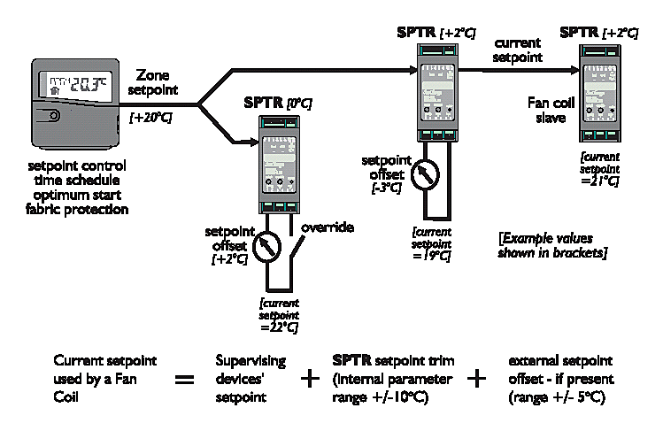
A Zone Controller may be used to determine the Setpoint for one or many Fan Coil Controllers. This is called Setpoint Supervision, (typically 20 Deg C).
A Fan Coil Controller may have a Local Setpoint Adjuster which is a simple wall-mounted potentiometer wired directly into the Fan Coil Controller’s input terminals; adjusting this will adjust the offset value (limited to +/-5 Deg.C). The offset value and a value set on the internal parameter SPTR are added (or subtracted if the value is negative) to the setpoint set on SPFC to produce the operating setpoint for the controller. Note that using a simple potentiometer means that some of the energy saving benefits given by the Zone Controller (e.g. resetting the setpoint to a default value at the start of each occupancy period) are not possible.
A Fan Coil Controller can also be used to provide Setpoint Supervision for a group of “Slave” Fan Coils; this would be used when an Open-Plan area is fed by several Fan Coils, and only one Local Setpoint Adjuster is required. The Local Setpoint Adjuster is wired to one of the Fan Coil Controllers, which then becomes the “Master” of the group. It will send its setpoint set on SPFC plus the offset applied by the Setpoint Adjuster plus any value set on SPTR to all of the “Slave” Fan Coils registered to it (see Master/Slave diagram) which will then use the resultant value as their own SPFC value. Individual trims to this setpoint can be set up in each “Slave” using its SPTR parameter, if desired.

Occupancy Times and Local Override

Occupation times for one, or many Fan Coil Controllers (up to 200) are set at a Zone Controller. The Occupancy Times may be overridden by the Override pushbutton on the Zone Controller in the usual way, giving configurable timed extension to occupancy (see Zone Controller Data Sheet).
Additionally, a local switch may be used in order to put the Fan Coil Controller into an Occupied State; this can either be used exclusively to control occupancy (e.g. a Meeting Room) or it can be used in conjunction with a Zone Controller to provide an extension to occupancy. In either case, the Controller requires a maintained contact closure (latching switch) in order to give an Occupied State; if a timed extension is desired, an external timed latching contact must be used. The parameter INMD is used to determine whether the external signal is to be used exclusively, or as an OR function with a Zone Controller’s Occupation Times.

FCU operation with remote User switch/Trim Pot or interlock

The supply sensor can be replaced by a switch which when made will force the FCU to Occupied.
This is achieved by adding an extra config variable input mode INMD. The following values are supported:
INMD = 0
Normal operation
Input measures Off Coil temperature
INMD = 1
Occupied is External AND normal occupation (window contact)
INMD = 2
Occupied is External OR normal occupation (outside normal hours)
INMD = 3
Occupation controlled by external signal only
INMD = 4
Input used as an external alarm, alarm state defined by ALST

Specification of Trim pot changed to match Sontay standard product.

If the switch is wired in series with a 1K resistor and a 10K potentiometer Occupied/ Non occupied plus a 5 degree trim (operational only whilst occupied) is possible. The low resistance equates to maximum negative trim.
The range of the applied Trim can be varied using configuration variable TRRG (Trim Range) in the range +/-0.0 to 10.0 degC. The centre zero and range accuracy of the Trim pot have been improved in version 4c1 onwards.
A resistance between 0 and 20K ohm will be considered to be Occupied, non Occupied is guaranteed for resistance values above 100K. The voltage generated by the pot will be converted to a setpoint Trim only for control modes SPTY 0 or 1
If the setpoint type SPTY of the controller is set to 2, this is where it receives heating and cooling demands from the supervising Zone Controller or Fan Coil Controller, then if the input mode INMD is set to force Occupation then an alarm will be raised INVD which indicates Invalid Configuration settings. The Fan Coil cannot operate without the demand signals from the Zone so forcing Occupation is not a valid option.

Occupation Priorities

There are many ways in which a Fan Coil Controller can be brought into Occupation. The following lists them in increasing priority:
PRIORITY
 
1
Occupation based on SPTY from Master
2
External input ON in INMD 2 or 3 will force ON
3
Change of Sontay switch to speed 1-3 when otherwise not occupied will force ON
4
External input OFF in INMD 1 or 3 will force OFF
5
Occupation Override from InSite or Doorway
6
Sontay switch in OFF position will force OFF
7
Alarm shut down
8
Manual HAND , brings outputs ON regardless of Occupation state
9
Fan Speed Priorities

Window Contact, General Alarm or Monitoring

A Volt-free window contact may be wired into the Controller’s input terminals and used to disable the Fan Coil if the Window is opened, preventing energy wastage. This function could also be applied to other inputs which would require the Fan Coil to shut down, e.g. Condensate Tray Full signal from a level switch. Alarms to the supervisor can be enabled or disabled using the ALRM parameter; the ALST parameter is used to set the contact sense. I.e. whether an opening or closing contact will generate an alarm.
The Input may be alternatively used for general monitoring, either with or without alarm generation (e.g. filter blocked).
The correct mode of operation is determined by the INMD parameter.

Alarm Handling

The FCU Controller may be set to ignore alarm conditions, report them to a SeaChange Doorway Supervisor (either locally connected to the system, or via an autodialling modem), or to both report alarms and take some control action. The ALRM parameter is used to select the desired Alarm Mode, whilst ALST is used to set the sense (ie. whether a closing or opening contact generates an alarm).
The FCU Controller generates an alarm if the sensor fails and also if the external alarm input is used.
The FCU Controller may be set to respond to the STOP System Stop Alarm which is generated by a Boiler Controller; this can be used to shut down the entire control system, or parts of it, if a particularly critical event occurs.

Pre Commissioning Checks

Power Up

On initial power up of the module there will be delay of between 10 to 60 seconds before the temperature LED lights. This delay has been incorporated so that when many fan coils are controlled on the same circuit their power requirements will be spread over this period. Once start up has been initiated, the valve outputs sequence to close the valves before control is initiated and until that process is completed (HPRD + CPRD) the manual override as described will be in-effective.

Setting the Stroke Time for Actuators

If the Select button is held pressed for a few seconds the status lamp will flash and the ‘B’ relay will energise to close the valve. When the valve is noted as closed and the Select button pressed again, the ‘A’ relay will energise causing the valve to open and start the timing cycle. When the valve reaches full stroke open, the Select button is pressed to record the Stroke Time and return the controller to the automatic mode. (For controllers with TP heating and cooling a similar process times both the heating and cooling valves).The times can also be checked and adjusted using the HPRD or CPRD parameter (recorded in tens of seconds).

Registration

Registration is the simple process by which logical connections are made between Controllers in a SeaChange system; it is done during commissioning and involves pressing buttons on the Controllers in a specific sequence. For further details of the registration process, see our ‘Commissioning Guide’ publication.

Address Allocation and System Housekeeping

Like all SeaChange Controllers, the Fan Coil Controllers must be registered with other modules in order to create a working system; one or more of the following registration procedures must be followed. During each of these procedures, the address of each Controller is allocated by the module that contains System Housekeeping. This could be a SeaChange Boiler Controller or a AHU Controller (for up to 100 Zone + FCU Controllers) or a Floor Controller (for up to 200 Zone + FCU Controllers). It is essential, therefore, that any SeaChange System contains one module with System Housekeeping; for more details, see Boiler, AHU or Floor Controller Data Sheets.

Occupancy Control, only from Zone Controller

The SPTY parameter in the FCU Controller must be set to 0, the Zone Controller is then put into Configuration Mode and the FCU Controller is registered to it. When the Zone Controller enters its occupancy mode, the FCU Controller’s registered to it will be enabled and will control to their occupied setpoints.

Occupancy Control + Setpoint Supervision from Zone Controller

The SPTY parameter in the FCU Controller must be set to 1, the Zone Controller is then put into Configuration Mode and the FCU Controller is registered to it. When the Zone Controller enters its occupancy mode, the FCU Controller’s registered to it will be enabled and will control to the setpoint in the Zone Controller.

Occupancy Control + Setpoint Supervision from a ‘Master’ Fan Coil Controller

The ‘Master’ Fan Coil Controller must be operating in SPTY 0 or 1 with its own return air sensor. ‘Slaves’ may have local sensors, but do not need them (see Setpoint Supervision and Local adjustment). The ‘Slave’ FCU Controller SPTY parameter must be set to 2 then the ‘Master’ FCU Controller is put into Configuration Mode registering the ‘Slave’ FCU Controller to it.
Occupancy of the ‘Slaves’ will now be taken from the ‘Master’; any setpoint change made at the ‘Master’ (whether from a Local Setpoint adjuster, or Setpoint Supervision change from a Zone Controller) will be reflected at the ‘Slaves’.

Demand Collation - Heat and Cool Sources

Heating and Cooling demand signals from the Fan Coil Controllers are automatically collated and are fed back to a provider of heat (or ‘cool’) - for instance, the Boiler Controller or a CT Pumpset. This is done by putting the Heat (or Cool) source into Configuration Mode and registering the FCU Controller to it.
For systems where the main plant is not controlled by SeaChange, the Floor Controller may be used to collate Heating and Cooling demand signals and present them as a series of volt-free contacts which can be used as inputs to the Legacy System in order to enable heating and/or cooling as appropriate. The Floor Controller is put into Configuration Mode and the FCU Controllers are registered to it.
For further details of the Floor Controller, see appropriate Data Sheet.

LED displays

Improvements have been made to the information provided to the user by the LEDs on the Controller.
When Slaving the controller to a master Zone or Fan Coil the completion of the Slave process is indicated by the error led flashing green five times.
When Registering to a heat source, the heat source number is flashed 'red' on the 'temperature' led (maximum 20 flashes)
When registering to a cool source, the cool source number is flashed 'yellow' on the temperature led (maximum 20 flashes)
If the controller is in an alarm condition which effects its control output, ALARM Manual or STOP then the 'temperature' led will flash red until the condition clears.

Accessing Configuration and Monitoring Parameters

Generally, Configuration Parameters are used to adjust settings from their factory defaults; Monitoring Parameters are used to monitor internal readings (such as temperature readings) during the Commissioning process.
The Parameters may be viewed, and in the case of Configuration Parameters, adjusted by one of two methods; either by using a Zone Controller connected to the network, or by using the SeaChange Doorway Supervisor.

Using the Zone Controller:

a) The Zone Controller must be connected to the network and registered (see Commissioning Guide for further details).
b) Put the Zone Controller into Configuration Mode by depressing Select and Override buttons for 10 seconds, until the CNFG legend appears on the display.
c) Press Select button momentarily on the target device (in this case, the selected Fan Coil Controller).
d) Hold down Select button on the Zone Controller, and rotate the rotary knob:
clockwise to view Monitoring Parameters
anticlock to view Configuration Parameters
e) When desired Configuration Parameter appears, release Select, hold down Override and turn knob to adjust the parameter (some Monitoring Parameters cannot be adjusted).

Using SeaChange Doorway:

Data Points may be added to a Doorway page to access/adjust any Configuration or Monitoring Parameter. Graphs of the Input Parameters and Heat/Cool output are also available. The code used to access an FCU Controller is Zn, where n is the Fan Coil Zone number. The code for each parameter is shown in the adjacent tables.
Further details of how to set up Doorway pages may be found in the SeaChange Doorway Manual, or in the online help facility supplied with SeaChange Doorway
The PC running SeaChange Doorway can be connected locally via a Serial Adaptor Module, or remotely using standard High-Speed Modems.In this manner all parameters can be monitored and adjusted remotely.

Manual Override

Allows the outputs to be exercised during comm-issioning and maintenance activities. Holding the Manual Override button pressed until the Status Lamp flashes green will cause the controller to be switched from automatic to manual control and the Fan will run.
Subsequent pressings of the manual override button will cause:
Press
Temp Lamp
Relay Output
1
Red
Htg Valve Open
2
Yellow
Htg Close, Clg Open
3
Green
Clg Close and returns to Auto Control
As this feature does not time out, care should be exercised to ensure the module is returned to the automatic mode on completion of the commissioning or maintenance activities.
Override can also be achieved via Doorway when AUTO can be set to manual mode and MANL used to set the output condition.

Doorway Override Options

Two override options are now available from Doorway.

Occupancy Override

This functions exactly the same as for a Zone Controller, Switch 1 set to zero selects Override mode and the state of switch 2 determines occupancy state.
The syntax

[Zn]W1(S)/Auto/Override/10/12/W2(S)

provides a single click to a dialog box which sets the correct state for both switches. The text can be changed to suit the application and the numbers determine the colours which are used to display the text.
Note the override mode will automatically terminate and return to Automatic when the required state for Occupancy matched the Overriden state. For example if the Fan coil is off becuase the window contact is not made, it can be Overriden ON and it will stay in Override until the normal Occupancy tests result in an on condition i.e. the window contact is fixed or the input mode INMD is changed.

HAND control

This option allows the Fan Coil outputs to be manually set for balancing or general testing. This uses switch 5 to select manual or hand mode and the value of MANL to set the output levels.
The syntax
[Zn]W5(S)/Hand/Auto/12/10/C83(V)
brings up a dialog box which allows Hand or Auto to be selected and also the value of the output to be entered in a text box or changed with a slider bar. The output can be set anywhere in the range 100 (full heat) to (-100) full cool. Note C83 is the fixed configuration variable MANL which is now used on all products which have universal manual code (4c1 or later).

Options and Product Codes

Fan Coil Controller

FCU / DIN / 3T / [driver option]

Driver options

Option

Output A

Output B

Output C

/ 001
Heating Valve raise
Heating Valve lower
Fan enable
/ 002
Cooling Valve raise
Cooling Valve lower
Fan enable
/ 003
Airside Damper raise
Airside Damper lower
Fan enable
/ 004
Thermal Heating Valve
Thermal Cooling Valve
Fan enable
/ 005
2 Pipe Heat/Cool Valve raise
2 Pipe Heat/Cool Valve lower
Fan enable


Input Configuration

Input 3-4
Supply temp sensor or Local setpoint adjustment (10k pot with 1k series resistor) and/or External Occupancy/Alarm/Window contact (optional)
Input 5-6‘temp’
Return temp sensor (optional)

ENER-G Controls

ENER-G House
Daniel Adamson Road
Salford
Manchester
M5 2DT

phone 0161 7457450
fax 0161 7457457

www.energ.com
www.seachange.co.uk
www.smartkontrols.co.uk