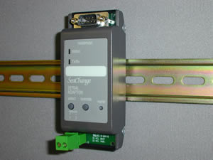
Feature Notes

Serial Adaptor
Standard Version (STD)

new features this issue are in RED
issue 5c1

SLT / DIN / STD

Main Features

Connects a SeaChange system to a Supervisor

Connects directly to a PC or to a High-Speed Modem or Cellphone

Network Powered - no auxilliary supply necessary

Configures connection automatically

DIN rail mounting

Supports baud rates 9600, 19200, 37400, 57600, 115200

Supports communications with Lighting Master and lighting system.

Supports configuration parameters in smartSwitch products

Description of Features

User Features

LEDs show status of module, indicating Modem or PC connection and Data Flow.
Override button can be used as manual reset.
Site name and 2 modem numbers can be stored.
Can store up to 5 alarms.
DIN rail mounting, suitable for panel mounting

Operation

This module provides an interface between either a PC (running InSite or SeaChange Doorway) or a modem. The module has a 9way ‘D’ type male connector for the RS232 connection. This mates with the standard cable supplied with most makes of external modem.
The SLT will automatically cycle through the connection possibilities until it detects a working setup. Consequently no special crossover/null modem cables are required.

Commissioning

On power up the SLT detects that an active RS232 connection is present and searches for the correct connection mode. The top lamp changes from Amber - no active RS232; to Red - PC connected; to Green - modem connected, as the options are tried, and will stop when the current connection mode is detected.
The baud rate, data speed, will be automatically detected provide the AUTO configuration parameter is set.
This function can be disabled using the AUTO and CONN parameters.
When used with the integrated modem (SLTi hardware 0034/001A) parameter SLTI should be set to match the operating mode.
The following parameters are set when in auto connection. This is for standard one to one serial cable.

SLT Connected To:

AUTO

BAUD

MODM

CONN

LED

PC
1
1
-
2
Red
US Robotics Modem
1
0->3
2
1
Green
Generic Modem
1
0->3
0
1
Green
TC35 Terminal Modem
0
1
3
1
Green

Modem Connection

Connect RS232 cable between the modem and SLT. Power up the modem first. When the SLT is powered it will detect the modem and send an ‘AT’ config. string, you will see this as a momentary flash of the Rx/Tx lamp. The SLT status lamp will be green while the modem is powered. The modem will automatically sense the baud rate.
It will then wait for valid data to be received. Either it will respond to an external call in or to a network alarm.

Cellular Modem (TC35T or M20)

The SLT can be used with a cellular modem, in particular the Siemens TC35T. To use this feature follow the following steps.
  1. Set configuration variable MODM to 3, this will also change the BAUD to 1 (baud rate of 19200) if you are using InSite or Doorway you will need to change the baud rate of the communications port to 19200 to continue using the SLT directly connected.
  2. Apply power and check the aerial connection on the TC35T.
  3. Connect the serial lead from the TC35T to the SLT, check that the top connection led changes from amber to red or green. When the TC35T has been successfully setup the lower status led on the SLT will fast flash 10 times.
It is recomended to set the AUTO configuration variable to 0, and CONN configuration variable to 1, as listed in the table above. These settings will have to be changed if you require a PC connection with the SLT at another time.
To check signal strength and error rate for the cellular connection scroll to SGNL 0 to 31 (31 is best), press display to refresh the value. Error rate is given on BERR 0 to 7, 0 is good 7 is bad (99 means not available or error). These values can only be read from the TC35T when it is not connected so do not try to get them when a dialled in connection is present.

Dial out alarms

Setting telephone numbers and site name.

If auto-dialled alarms are to be used, it is necessary to set a unique identifier for the site (so that the alarm can be traced), and the ‘phone number of the supervisor(s).
[s1]N0($) allows the site name to be displayed
[s1]N1(#) allows telephone number 1 to be displayed
[s1]N2(#) allows telephone number 2 to be displayed.
To edit these entries, create a temporary page using the syntax:
[s1]N0($="head_office") - will set the site name.
[s1]N1(#="01456 345123") - will set the 1st ‘phone no.
The number or site id can be up to 20 characters long. The telephone number can contain any special characters required dial the number correctly with the selected modem.
When an alarm is received by the SLT it will check to see if it is connected through a modem and if so will attempt to connect using number 1. If this fails it will retry after a one minute delay. It will continue to try number 1 at ever increasing time intervals, (number of tries in minutes) until it has tried 5 times.
The second number will then be tried initially at 5 minute intervals increasing to 10 minute intervals until it has been tried 5 times.
The SLT will then revert to the first number and try a further 10 times before it gives up. The total elapsed time between first and last try will be about 3.5 hours.
The telephone number must contain at least four digits (0-9) to be considered as a valid telephone number. If the number is not valid then the SLT will use the remaining number if valid or will ignore dial out completely.
The SLT will store the first five alarms received during the connection process, after this alarms will be lost.

PC Connection

Connect RS232 cable between the PC and SLT. The status lamp will remain Amber until InSite or SeaChange Doorway is started on the PC.
Start InSite or Doorway on the PC (the SLT status lamp will now go Red), check that the baud rate is set accordingly on the PC serial port (usually COM1). Select a page containing some data points to generate communications traffic, the Tx/Rx lamp will now flash to indicate data flow.
When InSIte or SeaChange Doorway is closed, even though the PC may remain switched on, the SLT status lamp will change from Red to Amber.

Registration

A maximum of four SLT modules can be used on one SeaChange network. The SLT must be registered to the System Housekeeping Module (e.g. boiler, floor controller) to have its address set.
When the SLT receives a registration message from any module it generates an alarm message which the Doorway Supervisor will log. The alarm message generated is:
[NODE REGISTRATION file name BLR2q Neuron identity 007895A21100]
This will not be automatically dialled out if a modem is connected.

InSite/Doorway Codes

Syntax used in the RS232 protocol is of the form:


[Address field]

Parameter field

(Data field)

Example
[z1]
S1
($,V)
 
see below
see ‘Doorway Codes’ on module datasheet
see Doorway online help file

Module Addresses:

Address field

Controller

[zn]
Zone, DHW or fan coil controllers
[an]
AHU controller
[hn]
Boiler or secondary circuit controller (Heating)
[cn]
Chiller or secondary circuit controller (Cooling)
[mn]
Monitoring Modules
[sn]
Serial adapter

Submodule Address Examples:

Address field

Controller

[z1a1]
1st Actuator registered to Zone1
[z1p1]
1st Pump changeover registered to Zone1
[a1cm]
AHU cascade registered to AHU1 (m = 1 or 2)
[a1m1]
1st Mixing damper registered to AHU1
[a1p1]
1st Preheater registered to AHU1
[a1fm]
Fan changeover registered to AHU1 (m = 1 or 2)
[a1h1]
1st Humidity controller registered to AHU1
[a1rm]
RH sensor registered to AHU1 (m = 1 or 2)

[#] Comms

Data points set up as [#]S1(V) etc will request information from the node which last sent a registration message.
The messages are requested using Neuron ID addressing indicated by the # symbol.
This could be used to present information on a generic page for test purposes, e.g. a page of config. variables. When the registration button is pressed the page will automatically display the data for that module.

Monitor Module Support

The SLT supports recovery of parameters from the monitor module using the device specifier "m". Alarms from the Monitor Module are now decoded with respect to the additional alarm flags, HIGH, LOW alarm etc.

Access to Network Variables

Limited support has been added to allow the value of network variables to be displayed on Doorway. This allows Doorway to be used to test intelligent sensors and also allows current valve position to be read from intelligent actuators.
The syntax needs to define the index of the network variable and the SNVT decoding to be used. The Doorway point is defined as:
[z1]Vn($) where n is the index of the network variable, the ($) define the decoding to be used as specified in the following table.

SNVT Type

Controller Doorway code

SNVT_temp
(V)
SNVT_temp_p
($)
SNVT_lev_cont
(%)
SNVT_lev_percent
(%)

Intelligent Actuators

[a1a1]V3(%) will return the current position of the actuator

Intelligent sensors

Outside sensor
[#]V1($) will return the current temperature
Temperature and RH
[#]V0($) will return Temperature
[#]V1(%) will return Relative Humidity

Subnet Node addressing

The Doorway syntax now allows direct addressing of modules using their subnet node address. This might be used in 'Externally bound' systems but can also be used to read data from intelligent sensors which are not directly supported by the module level syntax.
The syntax id [#sNn] where s=subnet, n=node
A sensor bound to a Boiler would be at address Subnet 11, Node 9, in general the sensor address will be the main module address with 9 added to the main module node address

Hiding missed replies

A new configuration parameter NRPL (no reply) which when set to 0 will suppress the showing of 'no reply' or '????' until two consecutive polls have failed. The default setting for this configuration variable is 1, i.e. ???? is displayed for each missed value.

Send Address SNDA

A configuration variable selects this feature which when set translates the {D/S/N} Domain, subnet, node address which is found on alarm messages to the more familiar [DxMy] module adress format used in Doorway and InSite

Send Complete SNDC

A configuration variable selects this feature, when set the SLT sends a 'transaction complete' message to the connected device. This message is used by the smartEinterface and will probably be used by future releases of InSite. This feature allows faster throughput through the SLT by removing idle times.
This parameter must be set when the SLT is connected to a smartEinterface

Trend Gateway (included in the standard version from issue 5b2)

IMPORTANT When used as a Gateway the SLT module must be the first registered SLT (i.e. node 1 subnet 30)

Features

This version of SLT provides Gateway functionality and the ability to transfer data for system integration between a SeaChange and Trend Building Management System. The following data as detailed below can be exchanged. Data exchange is configured using 'Text Attributes'. Multiple Zones are supported using SeaChange Floor Controller modules to pass these demands to the Gateway SLT, each Floor Controller can support upto 200 Zones.
The SLT will autodetect the connection type, however to avoid negotiation time the 'AUTO' detect config can be set to zero, and the connection type 'CONN' set to 4.
To avoid unnecessary traffic within the Trend system the SLT sends all demands as local global messages by default, i.e only Trend devices on the same Lan as the Gateway CNC will be able to receive the demand messages from the SeaChange system. However, setting the 'TMGG' to 1 will cause the SLT to deliver the SeaChange demand signals in global/global format to the Trend system and all devices on all Lans will be able to receive the demand messages. Note. This global/global mode of operation must only be selected when a Trend Internetwork is present.
Recipient Controller Attribute SEACHANGE

Data

Description

Item Attribute

Range

Units

SeaChange Heating demand
Highest heating demand from a group of devices (Fan coils/Zones) registed to Floor Controller module.
HTDM_x (see note below)
0 to 100
%
SeaChange Cooling demand
Highest cooling demand from a group of devices (Fan coils/Zones) registed to Floor Controller module.
CLDM_x (see note below)
0 to 100
%
SeaChange Outside temperature
Outside temperature from this Floor Controller module.
OSTP_x (see note below)
-30 to 100
Deg C
Where 'x' is the Floor Controller number 1 to 8.
Data can also be sent from Trend into the SeaChange system by the use of Trend Inter Controller Communications (IC Comms). These are sent in the digital bit format and directed to the Gateway Communication Node Controller (CNC).

Data

Description

Destination Bit Address

Range

Time and Date synchronization
Sending a (1) True to this location will cause the SeaChange Time and Day to be Synchronized with the Trend System. (It is recommended that this data be sent at 30 minute intervals.)
Byte 100 Bit 0
0 to 1
SeaChange 'STOP ALARM'
Sending a (1) True to this location will cause all SeaChange modules to respond to a system 'STOP ALARM' in there designated manner.(It is recommended that this data be sent at 30 minute intervals. Note the message will be sent on change by the Trend Controller.)
Byte 110 Bit 0
0 to 1
Note The SeaChange System allows for a default password of 1989 in the Trend Controllers, if a different password is used then at least one of the above IC Comms must be configured even if the facility is not used (i.e sending a 0 in the case of Time/Date synchronization. This allows the SeaChange System to deduce the password present in the Trend Controllers.

Alarms (Trend side)

The 'TAA' (Trend Alarm Address) and 'TAL' (Trend Alarm Lan) para's allows the user to specify an address within the Trend System to which SeaChange alarms should be directed.


Options and Product Codes

Serial Adaptor

SLT / DIN / [version] / [ option]

Options

Version

Option


/ STD /
/ 001
Standard version

ENER-G Controls

ENER-G House
Daniel Adamson Road
Salford
Manchester
M5 2DT

phone 0161 7457450
fax 0161 7457457

www.energ.com
www.seachange.co.uk
www.smartkontrols.co.uk